Value extractor

When a serial communication, like e.g. CAN, LIN or SENT is decoded, stream of data is obtained. This data usually contains one or more specific values that need to be monitored. The Value Extractor I/O can be used to extract such values from the data stream and present them in a graph, meter and/or table sink.
The Value Extractor I/O is connected to the output of a decoder I/O. Supported decoder I/Os are:
- I2C decoder I/O
- UART / Serial decoder I/O
- CAN decoder I/O
- SPI decoder I/O
- LIN decoder I/O
- DMX512 decoder I/O
- SENT decoder I/O
- FlexRay decoder I/O
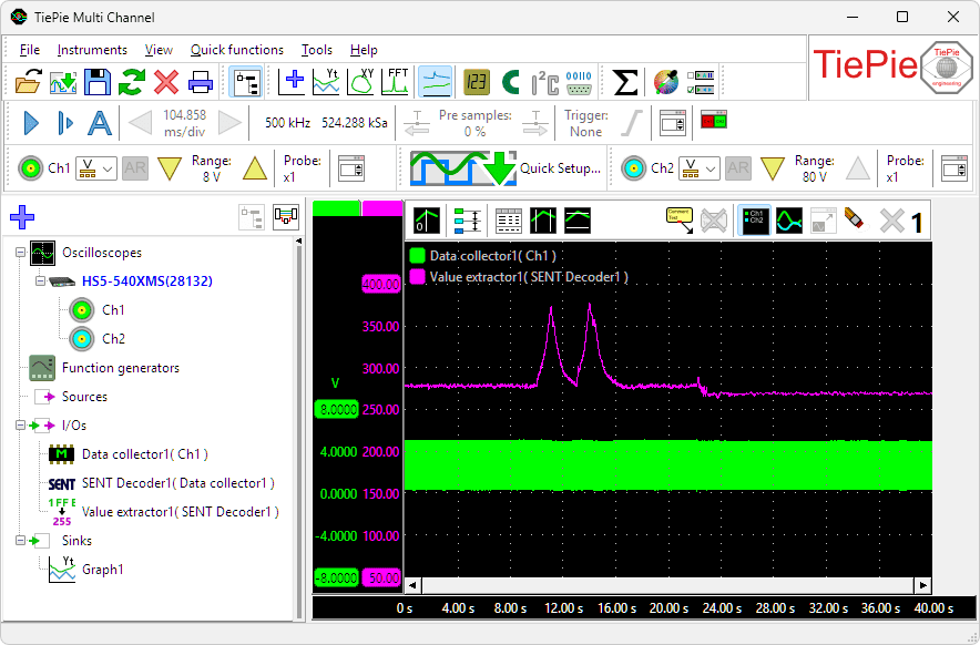
Below a measurement on a SENT bus, where the data is decoded by a SENT decoder and a specific sensor value is extracted with a Value extractor I/O and shown in the graph.
Value extractor properties
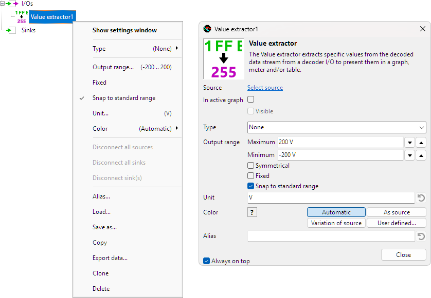
To control the behavior of the Value extractor I/O, several properties and actions are available.
These can be accessed through a popup menu which is shown when the I/O is right clicked in the Object screen.
The properties can also be accessed through its settings window which is shown when the I/O is double clicked in the Object screen.
To open the Object screen, click the  Show object screen button.
By default, the settings window only shows the most used settings. When Advanced is ticked, the extended window with all settings is shown. See also the program settings.
Type
When no decoder is connected yet to the Value extractor, the setting Type is used to determine for which protocol values have to be extracted. Possible values are:
- None
- I2C Value extractor
- CAN value extractor
- CANopen value extractor
- J1939 value extractor
- UART value extractor
- SPI value extractor
- LIN value extractor
- DMX512 value extractor
- SENT value extractor
- FlexRay value extractor
When setting Type to a value other than None, additional properties specific for the selected protocol decoder become available in the Value extractor I/O.
When a type is selected and the Value extractor is then connected to a different decoder, the type of the connected decoder overrules the manually selected type.
When connected to a specific protocol decoder I/O, properties specific for that protocol decoder become available in the Value extractor I/O. Select the tab for the properties of the required protocol decoder.
 I2C
I2C CAN
CAN CANopen
 J1939
J1939 UART
UART SPI
SPI LIN
LIN DMX512
 SENT
SENT FlexRay
I2C Value extractor specific properties
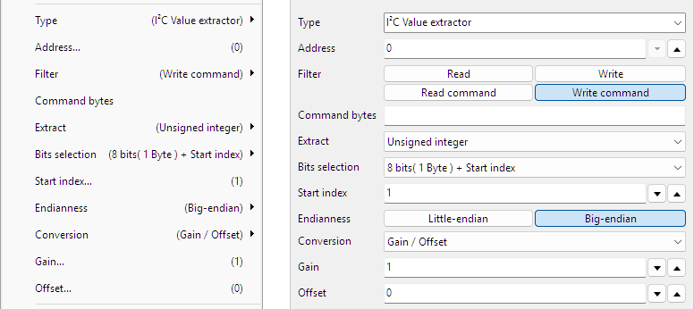
Address
I2C messages are always to and from a specific device on the bus, with a specific address. Selecting the required address makes the Value extractor monitor only messages to and from that address.
Filter
Based on the selected filter, specific messages can be filtered from the transmitted data on the bus.
| Filter | Description |
|---|---|
| Read | Read instructions are filtered out |
| Write | Write instructions are filtered out |
| Read command | Read instructions with a specific command are filtered out |
| Write command | Write instructions with a specific command are filtered out |
Command bytes
When filter Read command or Write command are selected, the Command bytes can be entered here.
Extract
It is possible to extract a generic value, either an integer, an unsigned integer or a floating point number from the data field in the message.
- Integer
- Unsigned integer
- Floating point
Bits selection
It is possible to define which bits must be used from the data field in the message to use for the required value. It can either be a range of bits together with a starting position, or an expression can be used to define which bits need to be used. The options are:
- All
- 8 bits (1 Byte) + Start index
- 16 bits (2 Bytes) + Start index
- 24 bits (3 Bytes) + Start index
- 32 bits (4 Bytes) + Start index
- 40 bits (5 Bytes) + Start index
- 48 bits (6 Bytes) + Start index
- 56 bits (7 Bytes) + Start index
- 64 bits (8 Bytes) + Start index
- Expression
Start index
When selecting a sub range of bits from the total data field on the message, the Start index is used to indicate where this sub range starts.
Expression
By using a special Expression, specific bytes or bits can be selected to extract, to form the requested value.
Bytes are counted starting at 1. Bits are counted starting at 0, where the least significant bit is right most. An example for 4 bytes is shown here:

The table below shows some expression examples with explanations.
| Expression | Description | Note |
|---|---|---|
| 1 2 | Extract bytes 1 and 2 and combine them to a 16 bit word | Big endian |
| 1 .. 4 | Extract bytes 1 to 4 and combine them to a 32 bit word | Big endian |
| 4 .. 1 | Extract bytes 4 to 1 in reversed order and combine them to a 32 bit word | Little endian |
| 1[3..0] .. 4[7..4] | Extract bits 3 to 0 from byte 1, byte 2, byte 3 and bits 7 to 4 of byte 4 and combine them to a 24 bit word. | |
| (4 .. 3)[12..4] | Extract bytes 4 to 3 in reversed order. From the resulting 16 bit word, extract the bits 12 to 4 | |
| (4 .. 3)[4..12] | Extract bytes 4 to 3 in reversed order. From the resulting 16 bit word, extract the bits 4 to 12, in reversed order | Reverses bits |
| (4 .. 3)[15] (4 .. 3)[12..4] | Extract bytes 4 to 3 in reversed order. From the resulting 16 bit word, extract bit 15 Also extract bits 12 to 4 and place these behind the original bit 15. The result is a 10 bits word. | |
| ( 1[3..0] .. 4[7..4] )[3..2] | Extract bits 3 to 0 from byte 1, byte 2, byte 3 and bits 7 to 4 of byte 4 and combine them to a 24 bit word. From that 24 bit word, extract bytes 3 and 2 in reversed order and combine them to a 16 bit word. |
Endianness
Endianess is the order in which multiple bytes that form one value are transmitted over the bus. This is also the order in which the multiple bytes are stored in the data section of the message.
- Little-endian: the Least Significant Byte is sent first
- Big-endian: the Most Significant Byte is sent first
When decoding a multi byte value, the endianess must be set to the correct value, otherwise decoding errors are made and wrong values are decoded. Endinaness is only relevant when a generic value like an integer, unsigned integer or floating point number is extracted.
Conversion
The value that is extracted may require a conversion, to show it in a specific unit. A Conversion can be selected to convert the extracted value to a value in the required unit. Depending on the selected conversion, additional settings can become available.
None
No conversion is applied, the value that is extracted, is presented at the output of the Value extractor I/O.
Gain / Offset
The extracted value is converted using a gain and an offset that can be entered.
Output = ( Gain * extracted value ) + Offset
Gain
A Gain value that is multiplied with the extracted value.
Offset
An Offset value that is added to the extracted value.
CAN Value extractor specific properties
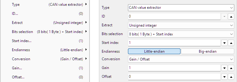
ID
Each CAN message contains an ID. By entering this ID in the corresponding field, only messages with this ID will be monitored.
Extract
It is possible to extract a generic value, either an integer, an unsigned integer or a floating point number from the data field in the message.
- Integer
- Unsigned integer
- Floating point
Bits selection
It is possible to define which bits must be used from the data field in the message to use for the required value. It can either be a range of bits together with a starting position, or an expression can be used to define which bits need to be used. The options are:
- All
- 8 bits (1 Byte) + Start index
- 16 bits (2 Bytes) + Start index
- 24 bits (3 Bytes) + Start index
- 32 bits (4 Bytes) + Start index
- 40 bits (5 Bytes) + Start index
- 48 bits (6 Bytes) + Start index
- 56 bits (7 Bytes) + Start index
- 64 bits (8 Bytes) + Start index
- Expression
Start index
When selecting a sub range of bits from the total data field on the message, the Start index is used to indicate where this sub range starts.
Expression
By using a special Expression, specific bytes or bits can be selected to extract, to form the requested value.
Bytes are counted starting at 1. Bits are counted starting at 0, where the least significant bit is right most. An example for 4 bytes is shown here:
The table below shows some expression examples with explanations.
| Expression | Description | Note |
|---|---|---|
| 1 2 | Extract bytes 1 and 2 and combine them to a 16 bit word | Big endian |
| 1 .. 4 | Extract bytes 1 to 4 and combine them to a 32 bit word | Big endian |
| 4 .. 1 | Extract bytes 4 to 1 in reversed order and combine them to a 32 bit word | Little endian |
| 1[3..0] .. 4[7..4] | Extract bits 3 to 0 from byte 1, byte 2, byte 3 and bits 7 to 4 of byte 4 and combine them to a 24 bit word. | |
| (4 .. 3)[12..4] | Extract bytes 4 to 3 in reversed order. From the resulting 16 bit word, extract the bits 12 to 4 | |
| (4 .. 3)[4..12] | Extract bytes 4 to 3 in reversed order. From the resulting 16 bit word, extract the bits 4 to 12, in reversed order | Reverses bits |
| (4 .. 3)[15] (4 .. 3)[12..4] | Extract bytes 4 to 3 in reversed order. From the resulting 16 bit word, extract bit 15 Also extract bits 12 to 4 and place these behind the original bit 15. The result is a 10 bits word. | |
| ( 1[3..0] .. 4[7..4] )[3..2] | Extract bits 3 to 0 from byte 1, byte 2, byte 3 and bits 7 to 4 of byte 4 and combine them to a 24 bit word. From that 24 bit word, extract bytes 3 and 2 in reversed order and combine them to a 16 bit word. |
Endianness
Endianess is the order in which multiple bytes that form one value are transmitted over the bus. This is also the order in which the multiple bytes are stored in the data section of the message.
- Little-endian: the Least Significant Byte is sent first
- Big-endian: the Most Significant Byte is sent first
When decoding a multi byte value, the endianess must be set to the correct value, otherwise decoding errors are made and wrong values are decoded. Endinaness is only relevant when a generic value like an integer, unsigned integer or floating point number is extracted.
Conversion
The value that is extracted may require a conversion, to show it in a specific unit. A Conversion can be selected to convert the extracted value to a value in the required unit. Depending on the selected conversion, additional settings can become available.
None
No conversion is applied, the value that is extracted, is presented at the output of the Value extractor I/O.
Gain / Offset
The extracted value is converted using a gain and an offset that can be entered.
Output = ( Gain * extracted value ) + Offset
Gain
A Gain value that is multiplied with the extracted value.
Offset
An Offset value that is added to the extracted value.
CANopen Value extractor specific properties
The Value extractor I/O extracts CANopen values directly from the decoded CAN messages, therefore it must be connected to the output of a CAN decoder I/O.
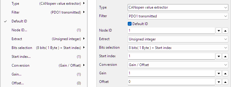
Filter
Based on the selected Filter, a specific message is filtered from the transmitted data on the bus:
| Filter | Description | |||
|---|---|---|---|---|
| SDO download/write | Service Data Object download/write | |||
| SDO upload/read | Service Data Object upload/read | |||
| PDO1 transmitted | Process Data Object 1 transmitted | |||
| PDO1 received | Process Data Object 1 received | |||
| PDO2 transmitted | Process Data Object 2 transmitted | |||
| PDO2 received | Process Data Object 2 received | |||
| PDO3 transmitted | Process Data Object 3 transmitted | |||
| PDO3 received | Process Data Object 3 received | |||
| PDO4 transmitted | Process Data Object 4 transmitted | |||
| PDO4 received | Process Data Object 4 received | |||
| Expression | Description | Note |
|---|---|---|
| 1 2 | Extract bytes 1 and 2 and combine them to a 16 bit word | Big endian |
| 1 .. 4 | Extract bytes 1 to 4 and combine them to a 32 bit word | Big endian |
| 4 .. 1 | Extract bytes 4 to 1 in reversed order and combine them to a 32 bit word | Little endian |
| 1[3..0] .. 4[7..4] | Extract bits 3 to 0 from byte 1, byte 2, byte 3 and bits 7 to 4 of byte 4 and combine them to a 24 bit word. | |
| (4 .. 3)[12..4] | Extract bytes 4 to 3 in reversed order. From the resulting 16 bit word, extract the bits 12 to 4 | |
| (4 .. 3)[4..12] | Extract bytes 4 to 3 in reversed order. From the resulting 16 bit word, extract the bits 4 to 12, in reversed order | Reverses bits |
| (4 .. 3)[15] (4 .. 3)[12..4] | Extract bytes 4 to 3 in reversed order. From the resulting 16 bit word, extract bit 15 Also extract bits 12 to 4 and place these behind the original bit 15. The result is a 10 bits word. | |
| ( 1[3..0] .. 4[7..4] )[3..2] | Extract bits 3 to 0 from byte 1, byte 2, byte 3 and bits 7 to 4 of byte 4 and combine them to a 24 bit word. From that 24 bit word, extract bytes 3 and 2 in reversed order and combine them to a 16 bit word. |
Endianness
Endianess is the order in which multiple bytes that form one value are transmitted over the bus. This is also the order in which the multiple bytes are stored in the data section of the message.
- Little-endian: the Least Significant Byte is sent first
- Big-endian: the Most Significant Byte is sent first
When decoding a multi byte value, the endianess must be set to the correct value, otherwise decoding errors are made and wrong values are decoded. Endinaness is only relevant when a generic value like an integer, unsigned integer or floating point number is extracted.
Conversion
The value that is extracted may require a conversion, to show it in a specific unit. A Conversion can be selected to convert the extracted value to a value in the required unit. Depending on the selected conversion, additional settings can become available.
None
No conversion is applied, the value that is extracted, is presented at the output of the Value extractor I/O.
Gain / Offset
The extracted value is converted using a gain and an offset that can be entered.
Output = ( Gain * extracted value ) + Offset
Gain
A Gain value that is multiplied with the extracted value.
Offset
An Offset value that is added to the extracted value.
J1939 Value extractor specific properties
The Value extractor I/O extracts J1939 values directly from the decoded CAN messages, therefore it must be connected to the output of a CAN decoder I/O. It replaces the J1939 decoder I/O.
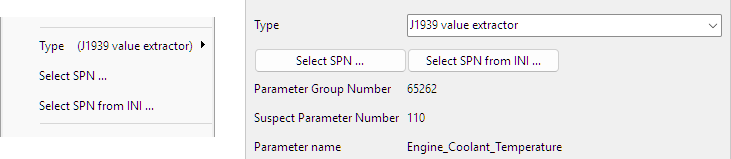
Select SPN ...
The action Select SPN ... opens a dialog in which an SPN can be selected to be extracted.
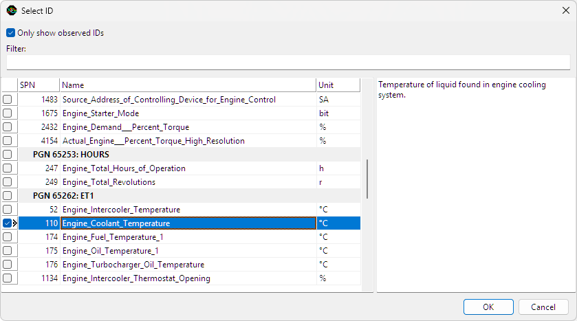
The dialog lists all J1939 standard Suspect Parameter Numbers (SPNs), ordered by Parameter Group Number (PGN). The text area at the right shows information about the highlighted PGN or SPN. When only show observed IDs is checked, the SPN list is reduced to only the ones contained in PGNs that were detected in the CAN input data.
To enable quick searching of parameters, further reducing the list is possible by using a filter string. Only PGNs and SPNs with a name satisfying the filter text are shown. By default, all filter keywords must be present in the name, but is also possible to exclude keywords by adding a minus symbol (-) in front of the keyword. The following filter for example will cause only PGNs and SPNs containing the word "temperature" but not "gas" to be listed:
temperature - gas
When the required ID is selected, clicking the OK button will extract the selected ID.
Select SPN from INI ...
The J1939 standard leaves room for custom PGNs and SPNs. Manufacturers can use these to transfer information that is not covered in the J1939 standard. Custom outputs can be added to the J1939 decoder to extract this information, by loading SPN information from an INI file.
Each J1939 message contains an eight byte block of data, called a parameter group. This parameter group contains one or more suspect parameters. The INI file describes how they are encoded in the data and what their function, unit and valid ranges are. You can create an INI file section for each desired SPN as in the following example:
; Field extraction information for [PGN.SPN]:
[61444.190]
Name=Engine_Speed
Position=24
Size=16
Gain=0.125
Offset=0
Min=0
Max=8031.88
Unit=rpm
Explanation:
- [PGN.SPN] The section header contains the Parameter Group Number and the Suspect Parameter Number, separated by a dot.
- Name: name of the parameter. This will also be the name of the output of the J1939 decoder.
- Position: bit position at which this parameter starts, where the very first bit position is 0 (zero).
- Size: size in bits of this parameter.
- Gain: multiplication factor to determine the actual value from the binary data.
- Offset: offset value to be added after the gain operation to get the actual value.
- Min: minimum valid value (optional).
- Max: maximum valid value (optional).
- Unit: unit of the suspect parameter.
The example values result in a suspect parameter with PGN 61444 and SPN 190, called Engine_Speed, with a valid range of 0 to 8031.88 rpm and a resolution of 0.125 rpm.
UART Value extractor specific properties
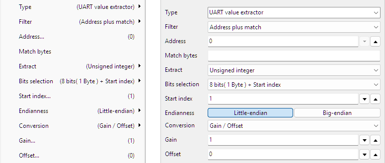
Filter
Based on the selected filter, specific messages can be filtered from the transmitted data on the bus. Some protocols using UART use 9 data bits and reserve bit number 9 as address flag, meaning that the other 8 bits contain an address.
| Filter | Description |
|---|---|
| After break | extraction starts after a Break |
| Match after break | extraction starts after a Break and a matching pattern |
| Match | extraction starts after a matching pattern |
| Address | extraction starts after a specific address |
| Address plus match | extraction starts after a specific address and a matching pattern |
Address
When filter Address or Address plus match is selected, an Address can be filled in here.
Match bytes
When filter Match, Match after break or Address plus match is selected, the field Match bytes is used to enter the matching pattern that is looked for.
Extract
It is possible to extract a generic value, either an integer, an unsigned integer or a floating point number from the data field in the message.
- Integer
- Unsigned integer
- Floating point
Bits selection
It is possible to define which bits must be used from the data field in the message to use for the required value. It can either be a range of bits together with a starting position, or an expression can be used to define which bits need to be used. The options are:
- 8 bits (1 Byte) + Start index
- 16 bits (2 Bytes) + Start index
- 24 bits (3 Bytes) + Start index
- 32 bits (4 Bytes) + Start index
- 40 bits (5 Bytes) + Start index
- 48 bits (6 Bytes) + Start index
- 56 bits (7 Bytes) + Start index
- 64 bits (8 Bytes) + Start index
- Expression
Start index
When selecting a sub range of bits from the total data field on the message, the Start index is used to indicate where this sub range starts.
Expression
By using a special Expression, specific bytes or bits can be selected to extract, to form the requested value.
Bytes are counted starting at 1. Bits are counted starting at 0, where the least significant bit is right most. An example for 4 bytes is shown here:
The table below shows some expression examples with explanations.
| Expression | Description | Note |
|---|---|---|
| 1 2 | Extract bytes 1 and 2 and combine them to a 16 bit word | Big endian |
| 1 .. 4 | Extract bytes 1 to 4 and combine them to a 32 bit word | Big endian |
| 4 .. 1 | Extract bytes 4 to 1 in reversed order and combine them to a 32 bit word | Little endian |
| 1[3..0] .. 4[7..4] | Extract bits 3 to 0 from byte 1, byte 2, byte 3 and bits 7 to 4 of byte 4 and combine them to a 24 bit word. | |
| (4 .. 3)[12..4] | Extract bytes 4 to 3 in reversed order. From the resulting 16 bit word, extract the bits 12 to 4 | |
| (4 .. 3)[4..12] | Extract bytes 4 to 3 in reversed order. From the resulting 16 bit word, extract the bits 4 to 12, in reversed order | Reverses bits |
| (4 .. 3)[15] (4 .. 3)[12..4] | Extract bytes 4 to 3 in reversed order. From the resulting 16 bit word, extract bit 15 Also extract bits 12 to 4 and place these behind the original bit 15. The result is a 10 bits word. | |
| ( 1[3..0] .. 4[7..4] )[3..2] | Extract bits 3 to 0 from byte 1, byte 2, byte 3 and bits 7 to 4 of byte 4 and combine them to a 24 bit word. From that 24 bit word, extract bytes 3 and 2 in reversed order and combine them to a 16 bit word. |
Endianness
Endianess is the order in which multiple bytes that form one value are transmitted over the bus. This is also the order in which the multiple bytes are stored in the data section of the message.
- Little-endian: the Least Significant Byte is sent first
- Big-endian: the Most Significant Byte is sent first
When decoding a multi byte value, the endianess must be set to the correct value, otherwise decoding errors are made and wrong values are decoded. Endinaness is only relevant when a generic value like an integer, unsigned integer or floating point number is extracted.
Conversion
The value that is extracted may require a conversion, to show it in a specific unit. A Conversion can be selected to convert the extracted value to a value in the required unit. Depending on the selected conversion, additional settings can become available.
None
No conversion is applied, the value that is extracted, is presented at the output of the Value extractor I/O.
Gain / Offset
The extracted value is converted using a gain and an offset that can be entered.
Output = ( Gain * extracted value ) + Offset
Gain
A Gain value that is multiplied with the extracted value.
Offset
An Offset value that is added to the extracted value.
SPI Value extractor specific properties
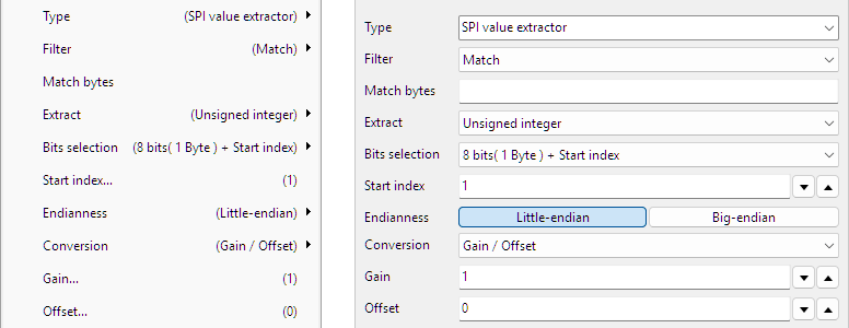
Filter
Based on the selected filter, specific messages can be filtered from the transmitted data on the bus.
- None
- Match
Match bytes
When filter Match is selected, the field Match bytes is used to enter the matching pattern that is looked for.
Extract
It is possible to extract a generic value, either an integer, an unsigned integer or a floating point number from the data field in the message.
- Integer
- Unsigned integer
- Floating point
Bits selection
It is possible to define which bits must be used from the data field in the message to use for the required value. It can either be a range of bits together with a starting position, or an expression can be used to define which bits need to be used. The options are:
- 8 bits (1 Byte) + Start index
- 16 bits (2 Bytes) + Start index
- 24 bits (3 Bytes) + Start index
- 32 bits (4 Bytes) + Start index
- 40 bits (5 Bytes) + Start index
- 48 bits (6 Bytes) + Start index
- 56 bits (7 Bytes) + Start index
- 64 bits (8 Bytes) + Start index
- Expression
Start index
When selecting a sub range of bits from the total data field on the message, the Start index is used to indicate where this sub range starts.
Expression
By using a special Expression, specific bytes or bits can be selected to extract, to form the requested value.
Bytes are counted starting at 1. Bits are counted starting at 0, where the least significant bit is right most. An example for 4 bytes is shown here:
The table below shows some expression examples with explanations.
| Expression | Description | Note |
|---|---|---|
| 1 2 | Extract bytes 1 and 2 and combine them to a 16 bit word | Big endian |
| 1 .. 4 | Extract bytes 1 to 4 and combine them to a 32 bit word | Big endian |
| 4 .. 1 | Extract bytes 4 to 1 in reversed order and combine them to a 32 bit word | Little endian |
| 1[3..0] .. 4[7..4] | Extract bits 3 to 0 from byte 1, byte 2, byte 3 and bits 7 to 4 of byte 4 and combine them to a 24 bit word. | |
| (4 .. 3)[12..4] | Extract bytes 4 to 3 in reversed order. From the resulting 16 bit word, extract the bits 12 to 4 | |
| (4 .. 3)[4..12] | Extract bytes 4 to 3 in reversed order. From the resulting 16 bit word, extract the bits 4 to 12, in reversed order | Reverses bits |
| (4 .. 3)[15] (4 .. 3)[12..4] | Extract bytes 4 to 3 in reversed order. From the resulting 16 bit word, extract bit 15 Also extract bits 12 to 4 and place these behind the original bit 15. The result is a 10 bits word. | |
| ( 1[3..0] .. 4[7..4] )[3..2] | Extract bits 3 to 0 from byte 1, byte 2, byte 3 and bits 7 to 4 of byte 4 and combine them to a 24 bit word. From that 24 bit word, extract bytes 3 and 2 in reversed order and combine them to a 16 bit word. |
Endianness
Endianess is the order in which multiple bytes that form one value are transmitted over the bus. This is also the order in which the multiple bytes are stored in the data section of the message.
- Little-endian: the Least Significant Byte is sent first
- Big-endian: the Most Significant Byte is sent first
When decoding a multi byte value, the endianess must be set to the correct value, otherwise decoding errors are made and wrong values are decoded. Endinaness is only relevant when a generic value like an integer, unsigned integer or floating point number is extracted.
Conversion
The value that is extracted may require a conversion, to show it in a specific unit. A Conversion can be selected to convert the extracted value to a value in the required unit. Depending on the selected conversion, additional settings can become available.
None
No conversion is applied, the value that is extracted, is presented at the output of the Value extractor I/O.
Gain / Offset
The extracted value is converted using a gain and an offset that can be entered.
Output = ( Gain * extracted value ) + Offset
Gain
A Gain value that is multiplied with the extracted value.
Offset
An Offset value that is added to the extracted value.
LIN Value extractor specific properties
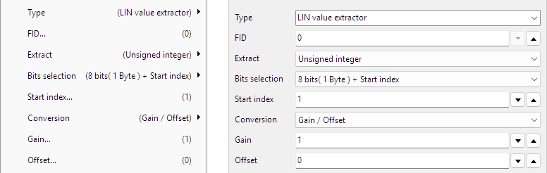
FID
LIN transmits messages with a Frame ID. Enter the required Frame ID in the FID to get the required messages.
Extract
It is possible to extract a generic value, either an integer, an unsigned integer or a floating point number from the data field in the message.
- Integer
- Unsigned integer
- Floating point
Bits selection
It is possible to define which bits must be used from the data field in the message to use for the required value. It can either be a range of bits together with a starting position, or an expression can be used to define which bits need to be used. The options are:
- All
- 8 bits (1 Byte) + Start index
- 16 bits (2 Bytes) + Start index
- 24 bits (3 Bytes) + Start index
- 32 bits (4 Bytes) + Start index
- 40 bits (5 Bytes) + Start index
- 48 bits (6 Bytes) + Start index
- 56 bits (7 Bytes) + Start index
- 64 bits (8 Bytes) + Start index
- Expression
Start index
When selecting a sub range of bits from the total data field on the message, the Start index is used to indicate where this sub range starts.
Expression
By using a special Expression, specific bytes or bits can be selected to extract, to form the requested value.
Bytes are counted starting at 1. Bits are counted starting at 0, where the least significant bit is right most. An example for 4 bytes is shown here:
The table below shows some expression examples with explanations.
| Expression | Description | Note |
|---|---|---|
| 1 2 | Extract bytes 1 and 2 and combine them to a 16 bit word | Big endian |
| 1 .. 4 | Extract bytes 1 to 4 and combine them to a 32 bit word | Big endian |
| 4 .. 1 | Extract bytes 4 to 1 in reversed order and combine them to a 32 bit word | Little endian |
| 1[3..0] .. 4[7..4] | Extract bits 3 to 0 from byte 1, byte 2, byte 3 and bits 7 to 4 of byte 4 and combine them to a 24 bit word. | |
| (4 .. 3)[12..4] | Extract bytes 4 to 3 in reversed order. From the resulting 16 bit word, extract the bits 12 to 4 | |
| (4 .. 3)[4..12] | Extract bytes 4 to 3 in reversed order. From the resulting 16 bit word, extract the bits 4 to 12, in reversed order | Reverses bits |
| (4 .. 3)[15] (4 .. 3)[12..4] | Extract bytes 4 to 3 in reversed order. From the resulting 16 bit word, extract bit 15 Also extract bits 12 to 4 and place these behind the original bit 15. The result is a 10 bits word. | |
| ( 1[3..0] .. 4[7..4] )[3..2] | Extract bits 3 to 0 from byte 1, byte 2, byte 3 and bits 7 to 4 of byte 4 and combine them to a 24 bit word. From that 24 bit word, extract bytes 3 and 2 in reversed order and combine them to a 16 bit word. |
Endianness
Endianess is the order in which multiple bytes that form one value are transmitted over the bus. This is also the order in which the multiple bytes are stored in the data section of the message.
- Little-endian: the Least Significant Byte is sent first
- Big-endian: the Most Significant Byte is sent first
When decoding a multi byte value, the endianess must be set to the correct value, otherwise decoding errors are made and wrong values are decoded. Endinaness is only relevant when a generic value like an integer, unsigned integer or floating point number is extracted.
Conversion
The value that is extracted may require a conversion, to show it in a specific unit. A Conversion can be selected to convert the extracted value to a value in the required unit. Depending on the selected conversion, additional settings can become available.
None
No conversion is applied, the value that is extracted, is presented at the output of the Value extractor I/O.
Gain / Offset
The extracted value is converted using a gain and an offset that can be entered.
Output = ( Gain * extracted value ) + Offset
Gain
A Gain value that is multiplied with the extracted value.
Offset
An Offset value that is added to the extracted value.
DMX512 Value extractor specific properties
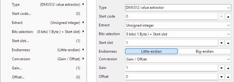
Start code
DMX512 transmits frames that contain several data bytes, here called "slots". The first slot, slot 0, is reserved for a "Start Code" that specifies the type of data in the packet. Next follow up to 512 slots of channel data, each containing one byte
In the field Start code a specific code can be entered to filter the correct messages from the data stream.
Extract
It is possible to extract a generic value, either an integer, an unsigned integer or a floating point number from the data field in the message.
- Integer
- Unsigned integer
- Floating point
Bits selection
It is possible to define which bits must be used from the data field in the message to use for the required value. It can either be a range of bits together with a starting position, or an expression can be used to define which bits need to be used. The options are:
- All
- 8 bits (1 Byte) + Start slot
- 16 bits (2 Bytes) + Start slot
- 24 bits (3 Bytes) + Start slot
- 32 bits (4 Bytes) + Start slot
- 40 bits (5 Bytes) + Start slot
- 48 bits (6 Bytes) + Start slot
- 56 bits (7 Bytes) + Start slot
- 64 bits (8 Bytes) + Start slot
- Expression
Start slot
When selecting a sub range of bits from the total data field on the message, the Start slot is used to indicate where this sub range starts.
Expression
By using a special Expression, specific bytes or bits can be selected to extract, to form the requested value.
Bytes are counted starting at 1. Bits are counted starting at 0, where the least significant bit is right most. An example for 4 bytes is shown here:
The table below shows some expression examples with explanations.
| Expression | Description | Note |
|---|---|---|
| 1 2 | Extract bytes 1 and 2 and combine them to a 16 bit word | Big endian |
| 1 .. 4 | Extract bytes 1 to 4 and combine them to a 32 bit word | Big endian |
| 4 .. 1 | Extract bytes 4 to 1 in reversed order and combine them to a 32 bit word | Little endian |
| 1[3..0] .. 4[7..4] | Extract bits 3 to 0 from byte 1, byte 2, byte 3 and bits 7 to 4 of byte 4 and combine them to a 24 bit word. | |
| (4 .. 3)[12..4] | Extract bytes 4 to 3 in reversed order. From the resulting 16 bit word, extract the bits 12 to 4 | |
| (4 .. 3)[4..12] | Extract bytes 4 to 3 in reversed order. From the resulting 16 bit word, extract the bits 4 to 12, in reversed order | Reverses bits |
| (4 .. 3)[15] (4 .. 3)[12..4] | Extract bytes 4 to 3 in reversed order. From the resulting 16 bit word, extract bit 15 Also extract bits 12 to 4 and place these behind the original bit 15. The result is a 10 bits word. | |
| ( 1[3..0] .. 4[7..4] )[3..2] | Extract bits 3 to 0 from byte 1, byte 2, byte 3 and bits 7 to 4 of byte 4 and combine them to a 24 bit word. From that 24 bit word, extract bytes 3 and 2 in reversed order and combine them to a 16 bit word. |
Endianness
Endianess is the order in which multiple bytes that form one value are transmitted over the bus. This is also the order in which the multiple bytes are stored in the data section of the message.
- Little-endian: the Least Significant Byte is sent first
- Big-endian: the Most Significant Byte is sent first
When decoding a multi byte value, the endianess must be set to the correct value, otherwise decoding errors are made and wrong values are decoded. Endinaness is only relevant when a generic value like an integer, unsigned integer or floating point number is extracted.
Conversion
The value that is extracted may require a conversion, to show it in a specific unit. A Conversion can be selected to convert the extracted value to a value in the required unit. Depending on the selected conversion, additional settings can become available.
None
No conversion is applied, the value that is extracted, is presented at the output of the Value extractor I/O.
Gain / Offset
The extracted value is converted using a gain and an offset that can be entered.
Output = ( Gain * extracted value ) + Offset
Gain
A Gain value that is multiplied with the extracted value.
Offset
An Offset value that is added to the extracted value.
SENT Value extractor specific properties
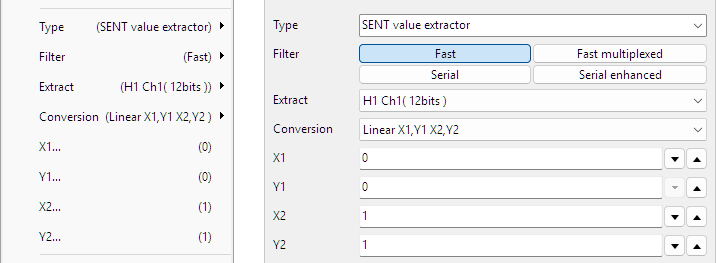
Filter
SENT can transfer several different types of data. The Value extractor can filter on a specific type and return only that type of data. Possible types of data are:
- Fast
- Fast multiplexed
- Serial
- Serial enhanced
Extract
Based on the selected filter, specific values can be extracted from the transmitted data on the bus. Refer to the data sheet of the sensor for the meaning of the specific values. It is also possible to extract a generic value, either an integer, an unsigned integer or a floating point number from the data field in the message.
| Fast | Fast multiplexed | Serial | Serial enhanced | |
|---|---|---|---|---|
| H1 Ch1 (12 bits) | F1_1 Ch (12 bits) | F2_3 Ch (16 bits) | Serial value | Serial value |
| H1 Ch2 (12 bits) | F1_1 App.data (8 bits) | F2_4 Counter (4 bits) | Integer | Integer |
| H2 Ch (12 bits) | F1_2 Ch (12 bits) | F2_4 Ch (16 bits) | Unsigned integer | Unsigned integer |
| H3 Ch (12 bits) | F1_3 Ch (12 bits) | F3_1 Ch1 (12 bits) | Floating point | Floating point |
| H4 Ch (12 bits) | F1_4 Counter (4 bits) | F3_1 Ch2 (8 bits) | ||
| H4 Counter (8 bits) | F1_4 Ch (12 bits) | F3_2 Ch1 (10 bits) | ||
| H5 Ch (12 bits) | F1_4 App.data (4 bits) | F3_2 Ch2 (10 bits) | ||
| H6 Ch1 (14 bits) | F1_5 Counter (4 bits) | F3_3 Ch1 (16 bits) | ||
| H6 Ch2 (10 bits) | F1_5 Ch (12 bits) | F3_3 Ch2 (12 bits) | ||
| H7 Ch1 (16 bits) | F1_6 Counter (4 bits) | F3_4 Ch1 (14 bits) | ||
| H7 Ch2 (8 bits) | F1_6 Ch (12 bits) | F3_4 Ch2 (14 bits) | ||
| Integer | F2_1 Ch (16 bits) | F3_5 Counter (4 bits) | ||
| Unsigned integer | F2_1 App.data (4 bits) | F3_5 Ch1 (12 bits) | ||
| Floating point | F2_2 Ch (16 bits) | F3_5 Ch2 (12 bits) | ||
| Integer | ||||
| Unsigned integer | ||||
| Floating point | ||||
Bits selection
When an Integer, an Unsigned integer or a Floating point number is extracted, it is possible to define which bits must be used from the data field in the message to use for the required value. It can either be a range of bits together with a starting position, or an expression can be used to define which bits need to be used. The options are:
- All
- 8 bits (1 Byte) + Start index
- 16 bits (2 Bytes) + Start index
- 24 bits (3 Bytes) + Start index
- 32 bits (4 Bytes) + Start index
- 40 bits (5 Bytes) + Start index
- 48 bits (6 Bytes) + Start index
- 56 bits (7 Bytes) + Start index
- 64 bits (8 Bytes) + Start index
- Expression
Start index
When selecting a sub range of bits from the total data field on the message, the Start index is used to indicate where this sub range starts.
Expression
By using a special Expression, specific bytes or bits can be selected to extract, to form the requested value.
Bytes are counted starting at 1. Bits are counted starting at 0, where the least significant bit is right most. An example for 4 bytes is shown here:
The table below shows some expression examples with explanations.
| Expression | Description | Note |
|---|---|---|
| 1 2 | Extract bytes 1 and 2 and combine them to a 16 bit word | Big endian |
| 1 .. 4 | Extract bytes 1 to 4 and combine them to a 32 bit word | Big endian |
| 4 .. 1 | Extract bytes 4 to 1 in reversed order and combine them to a 32 bit word | Little endian |
| 1[3..0] .. 4[7..4] | Extract bits 3 to 0 from byte 1, byte 2, byte 3 and bits 7 to 4 of byte 4 and combine them to a 24 bit word. | |
| (4 .. 3)[12..4] | Extract bytes 4 to 3 in reversed order. From the resulting 16 bit word, extract the bits 12 to 4 | |
| (4 .. 3)[4..12] | Extract bytes 4 to 3 in reversed order. From the resulting 16 bit word, extract the bits 4 to 12, in reversed order | Reverses bits |
| (4 .. 3)[15] (4 .. 3)[12..4] | Extract bytes 4 to 3 in reversed order. From the resulting 16 bit word, extract bit 15 Also extract bits 12 to 4 and place these behind the original bit 15. The result is a 10 bits word. | |
| ( 1[3..0] .. 4[7..4] )[3..2] | Extract bits 3 to 0 from byte 1, byte 2, byte 3 and bits 7 to 4 of byte 4 and combine them to a 24 bit word. From that 24 bit word, extract bytes 3 and 2 in reversed order and combine them to a 16 bit word. |
Endianness
Endianess is the order in which multiple bytes that form one value are transmitted over the bus. This is also the order in which the multiple bytes are stored in the data section of the message.
- Little-endian: the Least Significant Byte is sent first
- Big-endian: the Most Significant Byte is sent first
When decoding a multi byte value, the endianess must be set to the correct value, otherwise decoding errors are made and wrong values are decoded. Endinaness is only relevant when a generic value like an integer, unsigned integer or floating point number is extracted.
Conversion
The value that is extracted may require a conversion, to show it in a specific unit. A Conversion can be selected to convert the extracted value to a value in the required unit. Depending on the selected conversion, additional settings can become available. Refer to the documentation of the sensor that is being measured, for the correct Conversion that is required.
| Conversion | Description | Note |
|---|---|---|
| None | No conversion is applied, the value that is extracted, is presented at the output of the Value extractor I/O. | |
| Gain / Offset |
The extracted value is converted using a gain and an offset that can be entered. Output = ( Gain * extracted value ) + Offset |
|
| Linear X1,Y1 X2,Y2 |
The sensor has a linear characteristic that runs between two points, point (X1, Y1) and point (X2, Y2),
which coordinates must be entered. The equation of the characteristic is determined, resulting in a Gain and an Offset value, used to calculate the output value. Output = ( Gain * extracted value ) + Offset |
Sensor specific |
| Temperature (K) | The extracted value is converted to a temperature reading in K. | Sensor specific |
| Temperature (°C) | The extracted value is converted to a temperature reading in °C. | Sensor specific |
| Temperature high (K) | The extracted value is converted to a temperature reading in K. | Sensor specific |
| Temperature high(°C) | The extracted value is converted to a temperature reading in °C. | Sensor specific |
| Ratio (%) | The sensor generates a value, which is converted to a ratio in % | Sensor specific |
Gain and Offset
When Conversion Gain / Offset is selected, fields are available to enter a Gain value that is multiplied with the extracted value and an Offset value that is added to the extracted value.
X1, Y1, X2 and Y2
When Conversion Linear is selected, fields are available to enter values X1, Y1, X2 and Y2, to determine the characteristic of the sensor and calculate the output value.
FlexRay Value extractor specific properties
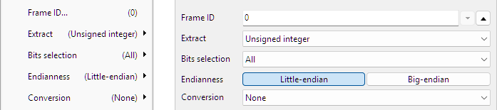
Frame ID
Enter the Frame ID here for the messages that need to be monitored.
Extract
Based on the selected filter, specific values can be extracted from the transmitted data on the bus. Refer to the data sheet of the sensor for the meaning of the specific values. It is also possible to extract a generic value, either an integer, an unsigned integer or a floating point number from the data field in the message.
- Integer
- Unsigned integer
- Floating point
Bits selection
When an Integer, an Unsigned integer or a Floating point number is extracted, it is possible to define which bits must be used from the data field in the message to use for the required value. It can either be a range of bits together with a starting position, or an expression can be used to define which bits need to be used. The options are:
- All
- 8 bits (1 Byte) + Start index
- 16 bits (2 Bytes) + Start index
- 24 bits (3 Bytes) + Start index
- 32 bits (4 Bytes) + Start index
- 40 bits (5 Bytes) + Start index
- 48 bits (6 Bytes) + Start index
- 56 bits (7 Bytes) + Start index
- 64 bits (8 Bytes) + Start index
- Expression
Start index
When selecting a sub range of bits from the total data field on the message, the Start index is used to indicate where this sub range starts.
Expression
By using a special Expression, specific bytes or bits can be selected to extract, to form the requested value.
Bytes are counted starting at 1. Bits are counted starting at 0, where the least significant bit is right most. An example for 4 bytes is shown here:
The table below shows some expression examples with explanations.
| Expression | Description | Note |
|---|---|---|
| 1 2 | Extract bytes 1 and 2 and combine them to a 16 bit word | Big endian |
| 1 .. 4 | Extract bytes 1 to 4 and combine them to a 32 bit word | Big endian |
| 4 .. 1 | Extract bytes 4 to 1 in reversed order and combine them to a 32 bit word | Little endian |
| 1[3..0] .. 4[7..4] | Extract bits 3 to 0 from byte 1, byte 2, byte 3 and bits 7 to 4 of byte 4 and combine them to a 24 bit word. | |
| (4 .. 3)[12..4] | Extract bytes 4 to 3 in reversed order. From the resulting 16 bit word, extract the bits 12 to 4 | |
| (4 .. 3)[4..12] | Extract bytes 4 to 3 in reversed order. From the resulting 16 bit word, extract the bits 4 to 12, in reversed order | Reverses bits |
| (4 .. 3)[15] (4 .. 3)[12..4] | Extract bytes 4 to 3 in reversed order. From the resulting 16 bit word, extract bit 15 Also extract bits 12 to 4 and place these behind the original bit 15. The result is a 10 bits word. | |
| ( 1[3..0] .. 4[7..4] )[3..2] | Extract bits 3 to 0 from byte 1, byte 2, byte 3 and bits 7 to 4 of byte 4 and combine them to a 24 bit word. From that 24 bit word, extract bytes 3 and 2 in reversed order and combine them to a 16 bit word. |
Endianness
Endianess is the order in which multiple bytes that form one value are transmitted over the bus. This is also the order in which the multiple bytes are stored in the data section of the message.
- Little-endian: the Least Significant Byte is sent first
- Big-endian: the Most Significant Byte is sent first
When decoding a multi byte value, the endianess must be set to the correct value, otherwise decoding errors are made and wrong values are decoded. Endinaness is only relevant when a generic value like an integer, unsigned integer or floating point number is extracted.
Conversion
The value that is extracted may require a conversion, to show it in a specific unit. A Conversion can be selected to convert the extracted value to a value in the required unit. Depending on the selected conversion, additional settings can become available.
None
No conversion is applied, the value that is extracted, is presented at the output of the Value extractor I/O.
Gain / Offset
The extracted value is converted using a gain and an offset that can be entered.
Output = ( Gain * extracted value ) + Offset
Gain
A Gain value that is multiplied with the extracted value.
Offset
An Offset value that is added to the extracted value.
Common properties and actions
Related information

I2C decoder
The I2C decoder I/O decodes analog data on the SDA and SCL lines of an I2C bus to I2C data.
UART / Serial decoder
The UART / Serial decoder I/O decodes analog data on a UART, RS232, RS485, MIDI, DMX, LIN or other compatible serial bus to serial data.
CAN decoder
The CAN decoder I/O decodes analog data to CAN data.
SPI decoder
The SPI decoder I/O decodes analog data on an SPI bus to SPI data.
LIN decoder
The LIN decoder I/O decodes analog data on a Local Interconnect Network bus to LIN message data.
SENT decoder
The SENT decoder I/O decodes analog signals on a SENT bus to SAE J2716 SENT messages.
DMX512 decoder
The DMX512 decoder I/O decodes analog signals on a DMX512 bus to DMX512 messages.